

Table of Contents
1. Why Should Wall Thickness Be Defined Early in Plastic Part Design?
Wall thickness should be addressed early in the product development process because it influences almost every aspect of the finished part, including strength, appearance, mold filling, cooling behavior, cycle time, and overall cost.
If the walls are too thin, the part may not have enough rigidity or strength to withstand ejection forces, assembly loads, or stresses encountered during service.
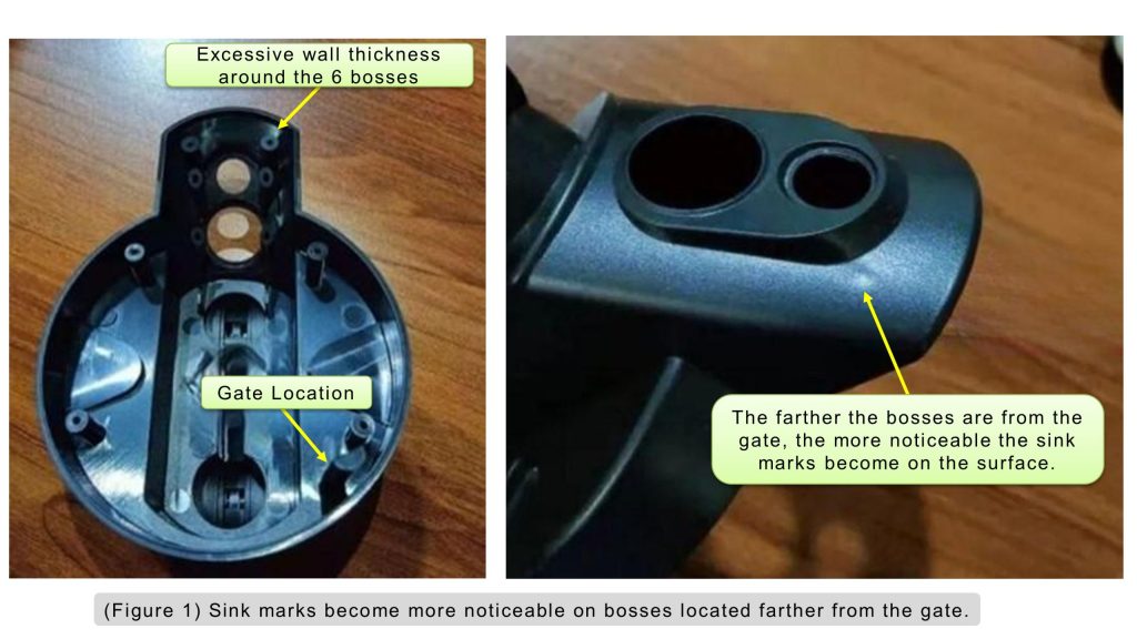
On the other hand, excessively thick walls consume more material and require longer cooling times. They also increase the risk of common molding defects such as sink marks, internal voids, and warpage. (Figure 1)
The goal, therefore, is not simply to make the part thicker to create a larger safety margin. The real objective is to find the right balance between structural performance, injection moldability, and manufacturing cost.
For mechanical engineers and product designers, understanding wall thickness guidelines early in the design process can prevent many issues from surfacing during mold trials and reduce the need for expensive design or tooling changes later.
2. Why Should Plastic Parts Be Neither Too Thin nor Too Thick?
Plastic behaves very differently from metal during manufacturing. In injection molding, molten resin must flow through the cavity and fill the entire part before the melt freezes.
When the wall becomes too thin, flow resistance increases and the melt loses heat more quickly as it travels through the cavity. As a result, filling the part becomes more difficult.
In some cases, higher injection speed and pressure may be required to achieve complete filling. If the molding machine and process window cannot compensate, defects such as short shots or localized deformation may occur.
Making the wall substantially thicker, however, is not a good solution either. Thicker sections take considerably longer to cool, which directly increases the molding cycle. According to the source material, doubling the wall thickness may increase cooling time by approximately four times.
Longer cooling time reduces production efficiency and raises the manufacturing cost per part.
More importantly, thick sections do not cool uniformly. The outer skin solidifies first while the material at the core remains hot and continues to shrink. This difference in cooling and volumetric shrinkage can result in sink marks, internal voids, or warpage.
These defects can affect not only the cosmetic appearance of the part but also its dimensional stability and structural performance.
3. Key Factors When Determining Plastic Part Wall Thickness
Wall thickness should never be selected based only on the overall size of the part. Engineers also need to consider the actual loading conditions, assembly requirements, geometry, and injection molding process. Several factors should be evaluated.
- (a) Structural strength: More thickness can improve strength, but excessive thickness may introduce molding defects.
- (b) Ejection: Thin parts may deform under ejection force.
- (c) Assembly loads: Screw fastening and snap-fits require sufficient local strength.
- (d) Metal inserts: Different shrinkage behavior between metal and plastic can create stress concentrations.
- (e) Impact resistance: The structure should distribute impact loads and avoid local cracking.
Areas around holes deserve particular attention. During mold filling, the melt may split around a hole and rejoin on the opposite side, forming a weld line. Because weld lines can have lower local strength than the surrounding material, poor wall design in these areas may create potential failure points.
4. Use the Minimum Wall Thickness That Still Meets the Design Requirements
As long as the part meets its structural, ejection, assembly, and end-use requirements, the wall thickness should generally be kept as low as practical.
A thinner, well-designed wall reduces material usage, lowers part weight, shortens cooling time, and can reduce the overall molding cycle and manufacturing cost.
In the past, designers sometimes increased wall thickness as a straightforward way to improve strength. In many cases, however, adding more plastic is neither the most efficient nor the most mold-friendly solution.
A better approach is often to increase stiffness through geometry. For example, reinforcing ribs can be added to support large surfaces, while curved or corrugated sections can increase section stiffness without adding a large amount of material.
These approaches allow engineers to improve structural performance while maintaining a more efficient wall section and avoiding unnecessary material buildup.
5. Uniform Wall Thickness Helps Reduce Injection Molding Defects
As a general rule, wall thickness should be kept as uniform as possible throughout an injection-molded part.
When wall thickness varies significantly, different regions cool and shrink at different rates. This can result in sink marks, internal voids, warpage, and dimensional variation.
Thickness variation also affects melt flow during filling. A sudden transition from a thick section to a thin section can change the local flow behavior and cooling rate. Depending on the geometry and material, this may contribute to visible surface defects or residual stress.
Abrupt thickness changes can also create stress concentrations under mechanical loading. For these reasons, designers should avoid sharp changes in wall section whenever possible. Transitions between different thicknesses should be gradual and smooth so that melt flow, cooling, and structural load transfer are more consistent.
6. What Should You Do When Uniform Wall Thickness Is Not Possible?
Perfectly uniform wall thickness is not always practical. Functional features, styling requirements, packaging constraints, and assembly interfaces may require certain areas of a part to be thicker than others.
When that happens, the goal should be to manage the transition rather than eliminate every thickness variation. A thick-to-thin transition should not occur abruptly. Instead, a gradual transition zone should be introduced between the two sections. This improves melt flow through the transition and reduces the likelihood of localized stress concentration.
According to the source material, one general guideline is to use a transition length of approximately three times the wall thickness. This helps reduce molding and structural problems associated with abrupt section changes.
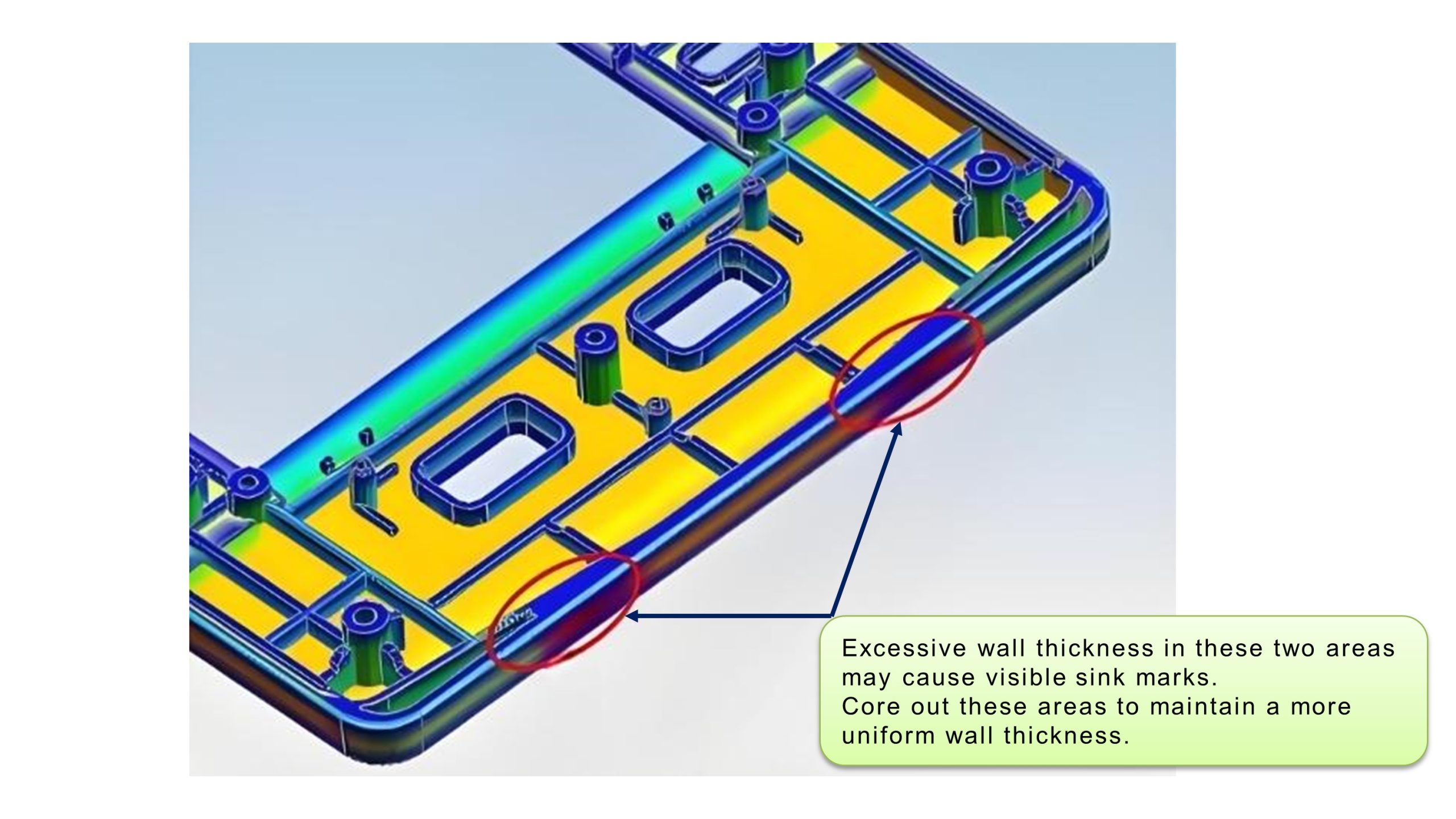
Locally thick areas can also be cored out. Instead of leaving a solid mass of plastic, designers can remove material from the interior and use ribs or other supporting features to maintain the required stiffness.
This is a common and effective way to reduce excessive material accumulation, minimize sink marks, and improve cooling uniformity while retaining the necessary structural performance.
In injection-molded part design, removing unnecessary mass is often more effective than simply making a section thicker.
7. Different Plastic Materials May Require Different Wall Thicknesses
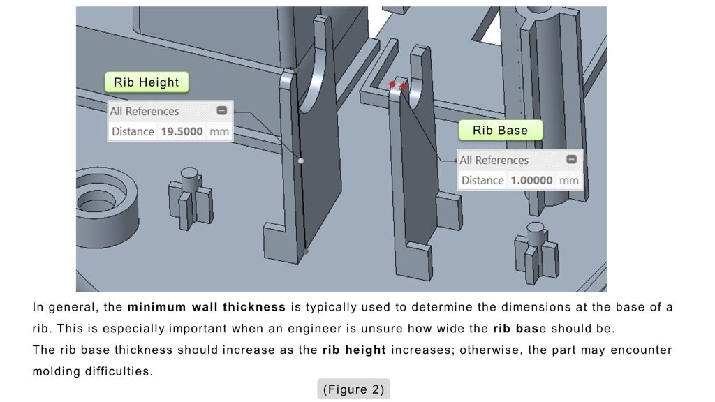
Recommended wall thickness ranges vary depending on the plastic material. (Table 1)(Figure 2)
| Plastic Material | Minimum Wall Thickness | Recommended Wall Thickness for Small Parts | Recommended Wall Thickness for Medium Parts | Recommended Wall Thickness for Large Parts |
|---|---|---|---|---|
| ABS | 0.6 | 1.00~1.40 | 1.40~2.00 | >2.00 |
| PC | 0.6 | 0.80~1.20 | 1.20~2.00 | >2.00 |
| PMMA | 0.6 | 0.80~1.50 | 1.50~2.20 | >2.20 |
| PC+ABS | 0.6 | 0.80~1.20 | 1.20~2.00 | >2.00 |
| PP | 0.6 | 0.80~1.20 | 1.20~2.00 | >2.00 |
| PE | 0.6 | 0.80~1.20 | 1.20~2.00 | >2.00 |
| POM | 0.8 | 1.00~1.50 | 1.50~2.20 | >2.20 |
| PA | 0.4 | 0.60~1.00 | 1.00~1.60 | >1.60 |
Even within the same resin family, the practical wall thickness range may vary with resin grade, filler content, flow characteristics, and the material supplier’s recommendations.
For example, two grades of the same polymer may have significantly different melt-flow behavior and may not perform equally well in a thin-wall application.
For this reason, when a design approaches either the minimum or maximum recommended wall thickness for a material, engineers should avoid relying solely on previous experience or generic design tables.
The resin supplier’s technical data and processing recommendations should be reviewed, and the specific grade should be confirmed before tooling is finalized.
This additional check can reduce the risk of filling, shrinkage, or dimensional problems during mold trials and helps ensure that the design is suitable for stable mass production.
8. Conclusion: Good Wall Thickness Design Is About Balance, Not Simply Adding Material
Good wall thickness design is ultimately about balancing structural performance, appearance, moldability, cycle time, and manufacturing cost.
Walls that are too thin can make mold filling more difficult and may leave the part vulnerable to deformation during ejection or assembly. Walls that are too thick increase material consumption and cooling time while also raising the risk of sink marks, voids, and warpage.
A practical design principle is therefore straightforward: use the minimum wall thickness that still satisfies the functional and manufacturing requirements of the part, and keep the wall as uniform as the design allows.
Where thickness variations are unavoidable, transitions should be gradual rather than abrupt. Locally thick sections should be cored out whenever practical, and structural features such as ribs, curved surfaces, or corrugated geometry can be used to improve stiffness without adding unnecessary material.
By applying these principles early in the design process, engineers can improve part performance, achieve more consistent injection molding, shorten cycle time, and reduce the risk of costly changes during mold trials and mass production.
9. Frequently Asked Questions
Q1:Why is uniform wall thickness important in plastic part design?
Uniform wall thickness helps ensure consistent cooling and shrinkage during injection molding. Uneven wall thickness can lead to defects such as sink marks, internal voids, warpage, dimensional instability, and stress concentration.
Q2:How should transitions between thick and thin sections be designed?
Wall thickness changes should be gradual rather than abrupt. A smooth transition helps improve material flow and reduce stress concentration. The source material suggests that the transition length can generally be designed at approximately three times the wall thickness.
Q3:How can engineers improve plastic part strength without increasing wall thickness?
Instead of simply making the part thicker, engineers can use structural features such as reinforcing ribs, curved or wave-shaped sections, and hollowed-out designs. These approaches can improve rigidity and support while limiting material usage and avoiding problems associated with excessively thick sections.
10. Further Reading
(10-1) Plastic Part Wall Thickness Design Guide: Thickness Range, Flow Length, and Shrinkage Control
Wall thickness is a critical factor in plastic part design, affecting strength, weight, dimensional stability, appearance, material usage, and manufacturability.
Good design is not simply about making walls thicker or thinner. The key is to balance structural requirements with material flow, cooling, and shrinkage.This article summarizes the key considerations for wall thickness design.
11. References and Additional Resources
This article draws on relevant technical books, literature, research materials, and publicly available sources. The primary references have been compiled in the “References and Book Sources” video for readers who wish to explore the subject in greater depth.
Any images, charts, technical data, or published materials cited or reproduced in this article remain the property of their respective authors, publishers, or other rights holders.
[1] Zhao, Longzhi, Zhao, Mingjuan, and Fu, Wei. Practical Handbook of Modern Injection Mold Design. China Machine Press, October 2012.
[2] Li, Huilai. Practical Examples of Product Structural Design. Publishing House of Electronics Industry, July 2013.
[3] Zhong, Yuan. Product Design Guidelines for Manufacturing and Assembly. China Machine Press, October 2011.
▶ Complete References and Source Materials — For more details, please watch the following video.