

Table of Contents
1. Why Wall Thickness Matters in Injection-Molded Part Design
Wall thickness is a key factor in injection-molded plastic part design. It affects mold filling, part strength, cooling time, shrinkage, surface quality, and production cost.
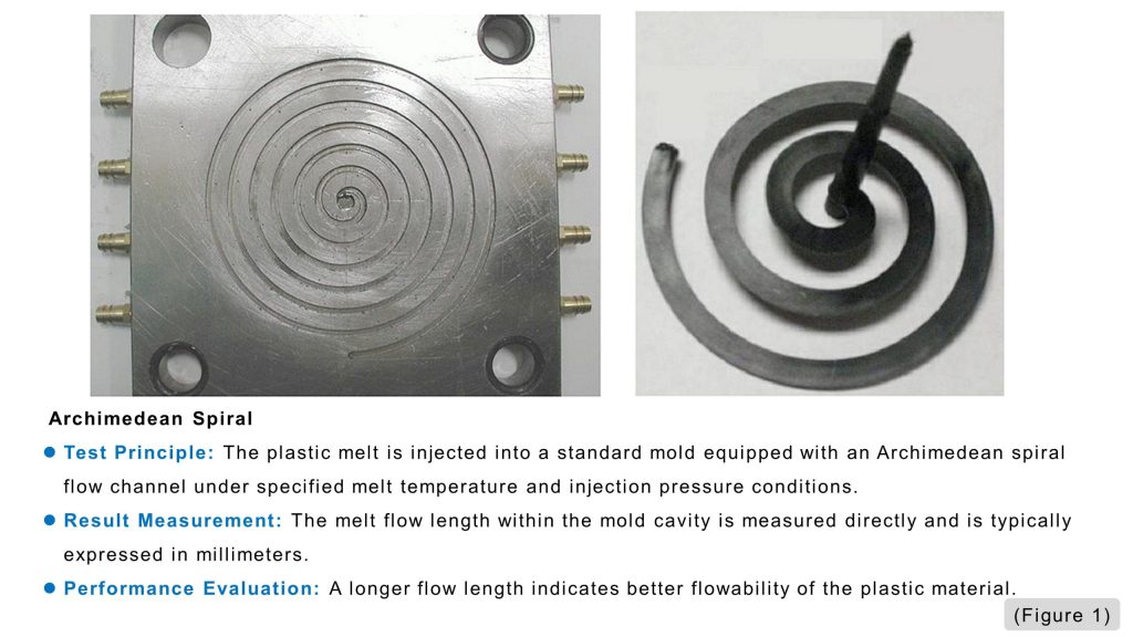
If the wall is too thick, the part may cool slowly and have a higher risk of sink marks, internal voids, and longer cycle times. If the wall is too thin, the molten plastic may not fill the cavity properly, especially when the flow path is long. Improper wall thickness design may cause:
- (a) Sink marks
- (b) Internal voids
- (c) Warpage
- (d) Cracking
- (e) Short shots
- (f) Long cooling times
Because of these risks, wall thickness should be reviewed together with the flow length-to-thickness ratio, or FLR. FLR helps confirm whether the selected plastic material can flow through the cavity at the chosen wall thickness.
In short, a good design should balance wall thickness, material flow behavior, product strength, and moldability from the early design stage.
2. Wall Thickness as a Basic Design Parameter
Wall thickness is the reference for many other features in a plastic part. Ribs, bosses, holes, fillets, and local reinforcement areas are usually designed based on the nominal wall thickness.
From a molding viewpoint, wall thickness affects how the polymer melt flows, how packing pressure is transferred, how the part cools, and how the material shrinks.
Many modern plastic products use thinner walls to reduce weight and material cost. However, thinner walls still need enough stiffness and strength. Increasing the overall wall thickness is not always the best solution. A better method is often to improve the structure. For example, designers can improve stiffness by:
- (a) Adding proper reinforcing ribs
- (b) Optimizing the part geometry
- (c) Using smooth corner radii
- (d) Avoiding unnecessary thick sections
- (e) Balancing strength, weight, and moldability
This approach helps the part meet functional needs without creating excessive material use or long cooling times.
(2-1) Keep Wall Thickness as Uniform as Possible
An injection-molded part is usually formed by many thin sections. If wall thickness changes too much, melt flow and cooling shrinkage become uneven. Uneven wall thickness can cause several problems:
- (a) Thick areas cool more slowly
- (b) Shrinkage becomes inconsistent
- (c) Packing pressure becomes harder to control
- (d) Sink marks may appear near thick sections
- (e) Warpage or internal stress may increase
For this reason, uniform wall thickness is a basic rule in plastic part design. In real products, perfect uniformity is not always possible. Some areas may need more thickness for strength, assembly, screw fastening, or appearance. In these cases, the goal is to control the thickness change carefully.
(2-2) Use Smooth Transitions Between Thick and Thin Sections
When a part has both thick and thin sections, the change should be gradual. Abrupt steps should be avoided because they can create stress concentrations and unstable flow.
For thermoplastic materials, the thicker adjacent section is generally recommended to be no more than about twice the thickness of the thinner section. For thermosetting plastics, the ratio is generally recommended to stay below about 3:1. A smooth transition helps:
- (a) Reduce stress concentration
- (b) Improve melt flow stability
- (c) Support better packing pressure transfer
- (d) Reduce sink marks and voids
- (e) Improve dimensional stability
From the flow-path viewpoint, thicker sections or larger cavity gaps are preferably placed upstream along the melt flow direction. This helps packing pressure transfer more effectively toward downstream areas during the packing stage.
(2-3) Typical Wall Thickness Ranges
Suitable wall thickness depends on material type, part size, strength requirements, and molding conditions. (Table 1) provides general reference ranges for typical wall thicknesses.
| Plastic Material | Minimum Wall Thickness |
Recommended Wall Thickness for Small Parts |
Recommended Wall Thickness for Medium Parts |
Recommended Wall Thickness for Large Parts |
||||
| Nylon | 0.45 | 0.75 | 1.60 | 2.4~3.2 | ||||
| Polyethylene | 0.6 | 1.25 | 1.6 | 2.4~3.2 | ||||
| Polystyrene | 0.75 | 1.25 | 1.6 | 3.2~4.5 | ||||
| Modified Polystyrene | 0.75 | 1.25 | 1.6 | 3.2~5.4 | ||||
| Acrylic (372) | 0.8 | 1.5 | 2.2 | 4~6.5 | ||||
| Rigid Polyvinyl Chloride | 1.15 | 1.6 | 1.8 | 3.2~5.8 | ||||
| Polypropylene | 0.85 | 1.45 | 1.75 | 2.4~3.2 | ||||
| Chlorinated Polyether | 0.85 | 1.35 | 1.8 | 2.5~3.4 | ||||
| Polycarbonate | 0.95 | 1.8 | 2.3 | 3~4.5 | ||||
| Polyphenylene Oxide | 1.2 | 1.75 | 2.5 | 3.5~6.4 | ||||
| Cellulose Acetate | 0.7 | 1.25 | 1.9 | 3.2~4.8 | ||||
| Ethyl Cellulose | 0.9 | 1.25 | 1.6 | 2.4~3.2 | ||||
| Acrylics | 0.7 | 0.9 | 2.4 | 3~6 | ||||
| Polyoxymethylene | 0.8 | 1.4 | 1.6 | 3.2~5.4 | ||||
| Polysulfone | 0.95 | 1.8 | 2.3 | 3~4.5 | ||||
| Note: The minimum wall thickness may vary depending on molding conditions | Unit : mm | |||||||
| (Table 1) Recommended Minimum and Common Wall Thicknesses for Thermoplastic Plastic Parts | ||||||||
These values are only starting references. The final wall thickness must still be checked based on the actual product. When a thin wall is selected, designers should confirm that the part has enough strength during:
- (a) Product use
- (b) Screw fastening
- (c) Assembly
- (d) Handling
- (e) Mold release and ejection
For medium and large plastic parts, wall thickness should not be decided only by experience. It should be reviewed through design checks, mechanical evaluation, mold flow analysis, and ejection risk assessment. For electrical parts, wall thickness may also need to meet insulation requirements.
(2-4) Thicker Walls Do Not Always Improve Quality
When a part seems weak, increasing wall thickness may look like the easiest solution. However, thicker walls can create new molding problems. Excessive wall thickness may cause:
- (a) More resin consumption
- (b) Heavier product weight
- (c) Longer cooling time
- (d) Longer molding cycles
- (e) Higher production cost
- (f) Higher risk of sink marks or internal voids
Cooling time is especially important. In general, cooling time is roughly proportional to the square of wall thickness. This means a small increase in thickness can create a much longer cooling cycle.
If the main issue is stiffness, designers should first consider rib design or structural optimization instead of simply increasing the overall wall thickness.
3. Flow Length Ratio: A Key Check for Filling Capability
Wall thickness explains how thick the part is, but it does not fully show whether the mold cavity can be filled. The flow length-to-thickness ratio, or FLR, is used to evaluate filling capability.
FLR helps designers understand whether the selected plastic material can flow to the end of the cavity under a specific wall thickness condition.
(3-1) What Is Flow Length Ratio?
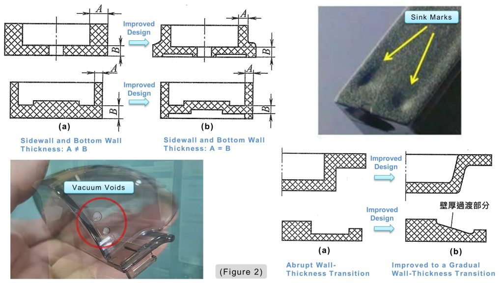
Flow length ratio compares how far the molten plastic must flow with the thickness of the flow path.
The basic formula is:
In simple terms, FLR asks one practical question:
Can the molten plastic reach the end of the cavity before it cools too much or loses too much pressure?
A long flow path and a thin wall create a high FLR. If the calculated FLR is higher than the material’s allowable value, the part may have a higher risk of short shots, unstable packing, or poor dimensional accuracy.
(3-2) How to Calculate FLR in Mold Design
For a simple part with uniform wall thickness, FLR can be estimated by dividing the main flow length by the wall thickness.
For parts with different thicknesses along the flow path, each section should be calculated separately. Then all section values are added together. For example:
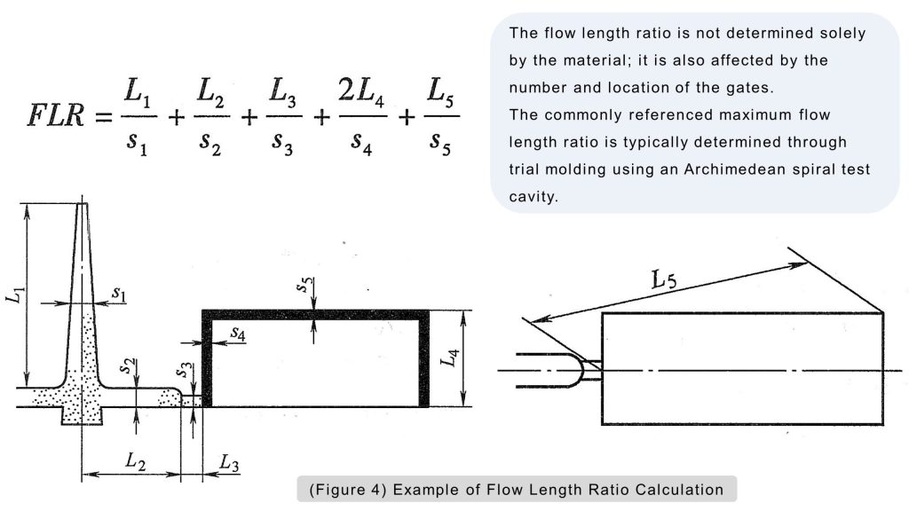
In actual mold design, the melt also flows through the sprue, runner, and gate before entering the cavity. These areas create pressure loss and should be included when evaluating filling capability.
(3-3) Why FLR Is Important
FLR connects product design with molding feasibility. A CAD model may look acceptable, but the part can still be difficult to mold if the flow path is too long or the wall is too thin. A proper FLR check can help identify:
- (a) Long flow paths
- (b) Thin sections near the end of filling
- (c) Areas far from the gate
- (d) Unbalanced flow paths
- (e) High pressure loss
- (f) Possible short-shot locations
By reviewing FLR early, designers can adjust gate location, wall thickness, material selection, or part geometry before mold manufacturing.
4. How Material Viscosity Affects FLR
Different plastics have different flow behavior. Material viscosity directly affects the maximum allowable flow length ratio.
High-viscosity materials do not flow as easily. They usually need shorter flow paths, thicker walls, better gate design, or higher injection pressure. Lower-viscosity materials can usually flow farther and may allow a higher FLR.
(4-1) Typical FLR Reference Values
Based on the reference values from the source material:
| (Table 2) Maximum Flow Length Ratios of Selected Plastic Melts | |||
| Plastic Material | Melt Temperature (°C) | Mold Temperature (°C) | FLRₘₐₓ |
| ABS | 218 – 260 | 38 – 77 | 160 – 175 |
| Polyoxymethylene (POM) | 182 – 200 | 77 – 93 | 140 – 250 |
| Acrylics | 190 – 243 | 49 – 88 | 130 – 150 |
| Polyamide 6 (PA6) | 232 – 288 | 77 – 93 | 150 – 300 |
| Polyamide 11 (PA11) | 191 – 194 | 77 – 93 | 150 – 300 |
| Polyethylene Terephthalate (PET) | 221 – 260 | 66 – 93 | 300 |
| Polycarbonate (PC) | 277 – 321 | 77 – 99 | 100 – 110 |
| Liquid Crystal Polymer + 30% GF | 310 – 340 | 66 – 93 | 300 |
| Low-Density Polyethylene (LDPE) | 98 – 115 | 15 – 60 | 275 – 300 |
| High-Density Polyethylene (HDPE) | 125 – 140 | 20 – 60 | 225 – 250 |
| Polypropylene (PP) | 168 – 175 | 15 – 60 | 350 |
| Modified Polystyrene | 203 – 310 | 93 – 121 | 200 – 250 |
| Polystyrene (PS) | 232 – 274 | 27 – 60 | 200 – 250 |
| Polyurethane (PU) | 170 – 204 | 27 – 66 | 200 |
| Polyvinyl Chloride (PVC) | 196 – 204 | 21 – 38 | 100 |
| Polyetherimide (PEI) | 350 – 415 | 65 – 175 | 200 |
| Note:Injection pressure = 80 ~ 90 MPa. When the flow-channel thickness is less than 2.5 mm, use 70%–80% of the lower-limit tabulated value. | |||
These values should be used as references, not fixed rules. Actual filling capability depends on part size, wall thickness, mold temperature, melt temperature, injection pressure, runner design, gate design, and processing conditions.
(4-2) Use FLR Values Carefully
FLR reference values are usually obtained under specific test conditions. Actual production conditions may be different.
When the wall thickness along the flow path is less than 2.5 mm, the reference FLR should be used more conservatively. Thin sections cool faster and create more flow resistance.
For critical parts, FLR should be checked together with mold flow analysis. Mold flow simulation can help predict filling pressure, weld lines, air traps, temperature distribution, and possible short shots.
5. Conclusion
Wall thickness is a key design parameter for injection-molded plastic parts. It affects filling, strength, cooling time, shrinkage, appearance, cost, and production stability.
A good design should keep wall thickness as uniform as possible. When thickness changes are needed, the transition should be smooth. The selected thickness should also match the material, part size, product function, assembly method, and molding process.
Simply increasing wall thickness is not always the best solution. Excessive thickness can increase weight, resin use, cooling time, cycle time, and cost. In many cases, well-designed ribs or structural optimization can improve stiffness more effectively.
Flow length ratio provides another important design check. By comparing flow distance with wall thickness, FLR helps designers confirm whether the selected material can fill the cavity successfully.
When wall thickness design and FLR evaluation are used together, the plastic part becomes easier to mold, more stable in production, and more suitable for mass production.
6. Frequently Asked Questions
Q1. Why should wall thickness be uniform?
Uniform wall thickness helps the melt flow more evenly and reduces uneven shrinkage. It also lowers the risk of sink marks, voids, warpage, cracking, and dimensional instability.
Q2: What is FLR used for?
FLR is used to check whether the melt can travel through the required flow length at a given wall thickness. An excessive FLR may indicate filling difficulty.
Q3. What does FLR mean in injection molding?
FLR means Flow Length Ratio. It is used to check whether molten plastic can flow through the mold cavity successfully under a given wall thickness and material condition.
7. Further Reading
(7-1) Plastic Part Wall Thickness Design Guide: Thickness Range, Flow Length, and Shrinkage Control
Wall thickness is a critical factor in plastic part design, affecting strength, weight, dimensional stability, appearance, material usage, and manufacturability.
Good design is not simply about making walls thicker or thinner. The key is to balance structural requirements with material flow, cooling, and shrinkage.This article summarizes the key considerations for wall thickness design. Click the image to read the full article.
8. References and Additional Resources
This article draws on relevant technical books, literature, research materials, and publicly available sources. The primary references have been compiled in the “References and Book Sources” video for readers who wish to explore the subject in greater depth.
Any images, charts, technical data, or published materials cited or reproduced in this article remain the property of their respective authors, publishers, or other rights holders.
[1] Zhao, Longzhi, Zhao, Mingjuan, and Fu, Wei. Practical Handbook of Modern Injection Mold Design. China Machine Press, October 2012.
[2] Li, Huilai. Practical Examples of Product Structural Design. Publishing House of Electronics Industry, July 2013.
[3] Zhong, Yuan. Product Design Guidelines for Manufacturing and Assembly. China Machine Press, October 2011.
▶ Complete References and Source Materials — For more details, please watch the following video.