

Table of Contents
1. Key Takeaways
When designing wall thickness for an injection-molded plastic part, consider:
- (a) Product strength and stiffness
- (b) Weight and material cost
- (c) Electrical and assembly requirements
- (d) Dimensional stability
- (e) Melt flow and filling capability
- (f) Sink marks, voids, shrinkage, and warpage
Wall thickness should also be evaluated together with material properties, flow length, gate location, and overall part size.
2. Why Is Wall Thickness Important?
Wall thickness directly affects both product performance and molding quality. Walls that are too thin may increase flow resistance, reduce strength, or cause incomplete filling.
Walls that are too thick increase material usage and cooling time. They may also create uneven shrinkage, sink marks, internal voids, or warpage.
For this reason, wall thickness should be determined according to product function, structural requirements, and molding conditions rather than appearance alone.
3. Basic Wall Thickness Design Guidelines
(3-1) Typical Wall Thickness Range
General plastic parts commonly use wall thicknesses of approximately 1–6 mm, with 2–3 mm being common in many applications. However, there is no universal value. The final wall thickness depends on:
- (a) Plastic material
- (b) Part size
- (c) Structural requirements
- (d) Molding conditions
Large plastic parts may require walls thicker than 6 mm when additional structural support is needed. Recommended values for thermoplastic and thermoset parts also vary with material and overall part dimensions (Table 1) (Table 2).
(3-2) Keep Wall Thickness Uniform
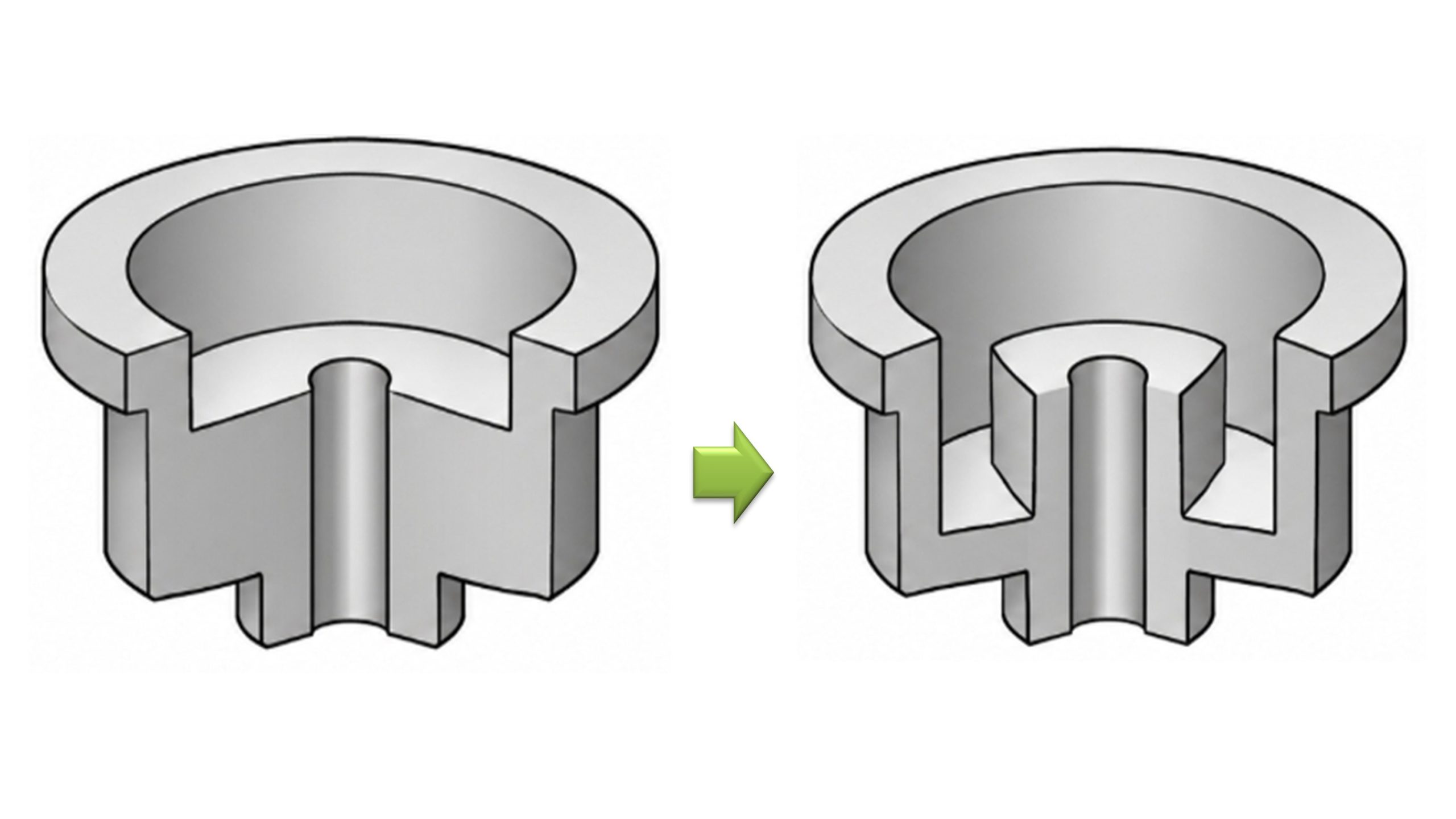
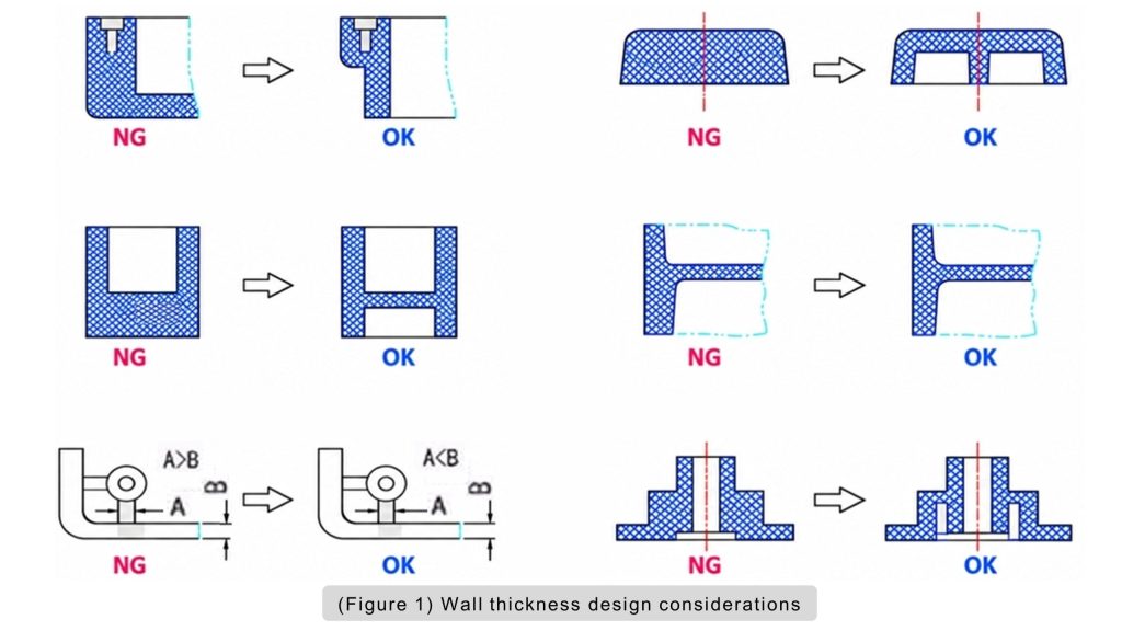
Uniform wall thickness is a basic rule in injection-molded part design. Large thickness variations can cause:
- (a) Uneven cooling
- (b) Differential shrinkage
- (c) Sink marks
- (d) Voids
- (e) Warpage
- (f) Dimensional instability
If a thickness change is necessary, avoid abrupt transitions. Use gradual transitions to improve melt flow and cooling consistency.
| Plastic Material | Molded Part Height | |||||
| <50 | 50~100 | >100 | ||||
| Phenolic Plastic with Powdered Filler | 1~2 | 2~3 | 5~6.5 | |||
| Phenolic Plastic with Fibrous Filler | 1.5~2 | 2.5~3.5 | 6~8 | |||
| Amino Plastic | 1 | 1.3~2 | 3~4 | |||
| Polyester Plastic with Glass-Fiber Filler | 1~2 | 2.4~3.2 | >4.8 | |||
| Polyester Plastic with Inorganic Filler | 1~2 | 3.2~4.8 | >4.8 | |||
| (Table 1) Recommended Wall Thickness Values for Thermosetting Plastic Parts | Unit:mm | |||||
| Plastic Material | Minimum Wall Thickness | Recommended Wall Thickness for Small Parts | Recommended Wall Thickness for Medium Parts | Recommended Wall Thickness for Large Parts | ||||
| Nylon | 0.45 | 0.75 | 1.60 | 2.4~3.2 | ||||
| Polyethylene | 0.6 | 1.25 | 1.6 | 2.4~3.2 | ||||
| Polystyrene | 0.75 | 1.25 | 1.6 | 3.2~4.5 | ||||
| Modified Polystyrene | 0.75 | 1.25 | 1.6 | 3.2~5.4 | ||||
| Acrylic (372) | 0.8 | 1.5 | 2.2 | 4~6.5 | ||||
| Rigid Polyvinyl Chloride | 1.15 | 1.6 | 1.8 | 3.2~5.8 | ||||
| Polypropylene | 0.85 | 1.45 | 1.75 | 2.4~3.2 | ||||
| Chlorinated Polyether | 0.85 | 1.35 | 1.8 | 2.5~3.4 | ||||
| Polycarbonate | 0.95 | 1.8 | 2.3 | 3~4.5 | ||||
| Polyphenylene Oxide | 1.2 | 1.75 | 2.5 | 3.5~6.4 | ||||
| Cellulose Acetate | 0.7 | 1.25 | 1.9 | 3.2~4.8 | ||||
| Ethyl Cellulose | 0.9 | 1.25 | 1.6 | 2.4~3.2 | ||||
| Acrylics | 0.7 | 0.9 | 2.4 | 3~6 | ||||
| Polyoxymethylene | 0.8 | 1.4 | 1.6 | 3.2~5.4 | ||||
| Polysulfone | 0.95 | 1.8 | 2.3 | 3~4.5 | ||||
| Note: The minimum wall thickness may vary depending on molding conditions | Unit:mm | |||||||
| (Table 2) Recommended Minimum and Common Wall Thicknesses for Thermoplastic Plastic Parts | ||||||||
4. Wall Thickness and Flow Length
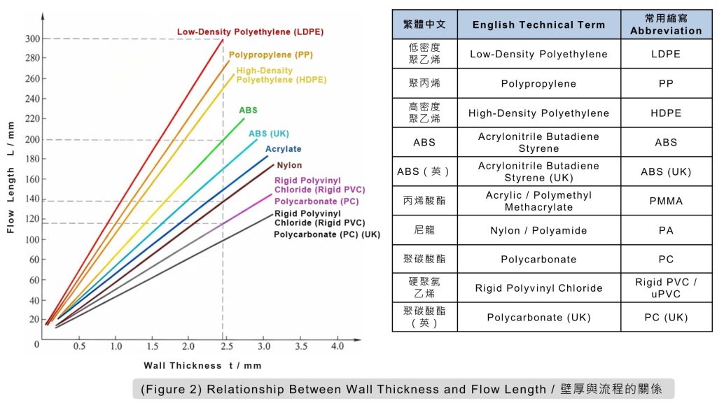
Wall thickness strongly affects how far molten plastic can flow through the mold cavity. In general:
- (a) Thicker walls allow longer flow distances.
- (b) Thinner walls create greater flow resistance.
The relationship between wall thickness t and flow length L can therefore be used to evaluate filling feasibility (Table 3 and Figure 2).
For example, when the wall thickness is 2.5 mm, the corresponding t-L relationship can be used to estimate whether the required flow distance is practical under normal molding conditions.
Wall thickness should therefore be checked together with gate location and the distance from the gate to the end of fill.
| Plastic Type | t – L Relationship | ||
| Good Flowability (e.g., Polyethylene, Nylon, etc.) |
5~6.5 | ||
| Medium Flowability (e.g., Acrylic, Polyoxymethylene) |
6~8 | ||
| Poor Flowability (e.g., Polycarbonate, Polysulfone, etc.) |
3~4 | ||
| (Table 3) Relationship Between Wall Thickness t and Flow Length L | |||
5. What If the Flow Length Is Too Long?
If the required flow distance exceeds the material’s practical filling capability, several design changes may be considered:
- (a) Increase the wall thickness
- (b) Add additional gates
- (c) Change the gate location
Increasing wall thickness can improve flow, but it may also increase weight, cooling time, shrinkage, and material cost.
Adding or relocating gates can reduce the required flow distance without significantly increasing the wall thickness.
The objective is to achieve reliable filling while maintaining product structure, appearance, and dimensional stability.
6. Wall Thickness Design Comparison
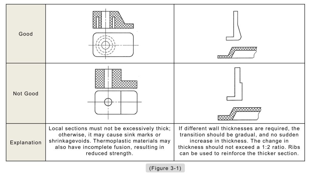
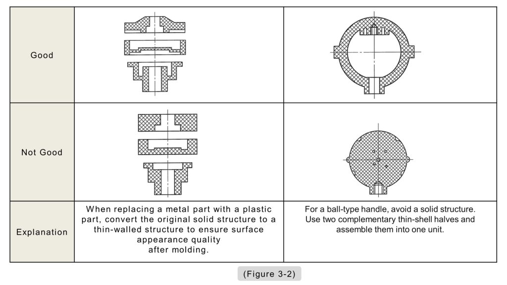
Good wall thickness design should minimize unnecessary thick sections and avoid sudden changes in section thickness. During DFM review, engineers should identify areas that may cause:
- (a) Excessive material buildup
- (b) Difficult filling
- (c) Uneven cooling
- (d) Sink marks
- (e) Warpage
Recommended and less desirable wall thickness designs are shown in (Figure 3-1) and (Figure 3-2).
7. Further Reading
(7-1) Uniform Wall Thickness in Plastic Part Design
Uniform wall thickness helps prevent uneven cooling and shrinkage, reducing the risk of sink marks, voids, warpage, and dimensional variation. Use gradual transitions to maintain smooth material flow and a consistent appearance.
(7-2) Plastic Part Wall Thickness and Flow Length Ratio (FLR) Design
Wall thickness and Flow Length Ratio (FLR) are key factors in injection-molded part design. Proper control of wall thickness, transitions, and flow length helps reduce sink marks, voids, warpage, and cracking while improving molding stability and production efficiency.
8. References and Additional Resources
This article draws on relevant technical books, literature, research materials, and publicly available sources. The primary references have been compiled in the “References and Book Sources” video for readers who wish to explore the subject in greater depth.
Any images, charts, technical data, or published materials cited or reproduced in this article remain the property of their respective authors, publishers, or other rights holders.
[1] Zhao, Longzhi, Zhao, Mingjuan, and Fu, Wei. Practical Handbook of Modern Injection Mold Design. China Machine Press, October 2012.
[2] Li, Huilai. Practical Examples of Product Structural Design. Publishing House of Electronics Industry, July 2013.
[3] Zhong, Yuan. Product Design Guidelines for Manufacturing and Assembly. China Machine Press, October 2011.
▶ Complete References and Source Materials — For more details, please watch the following video.